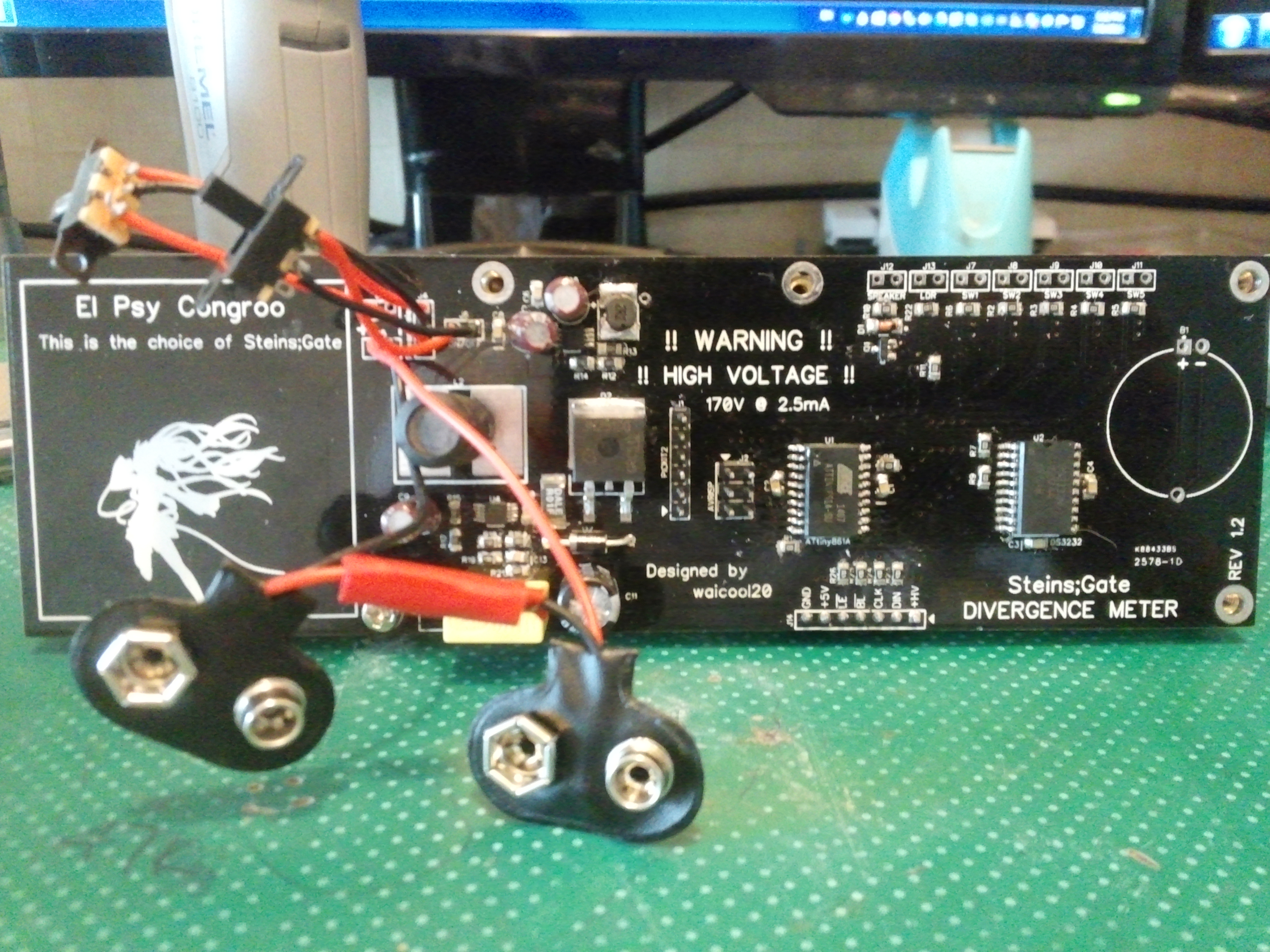
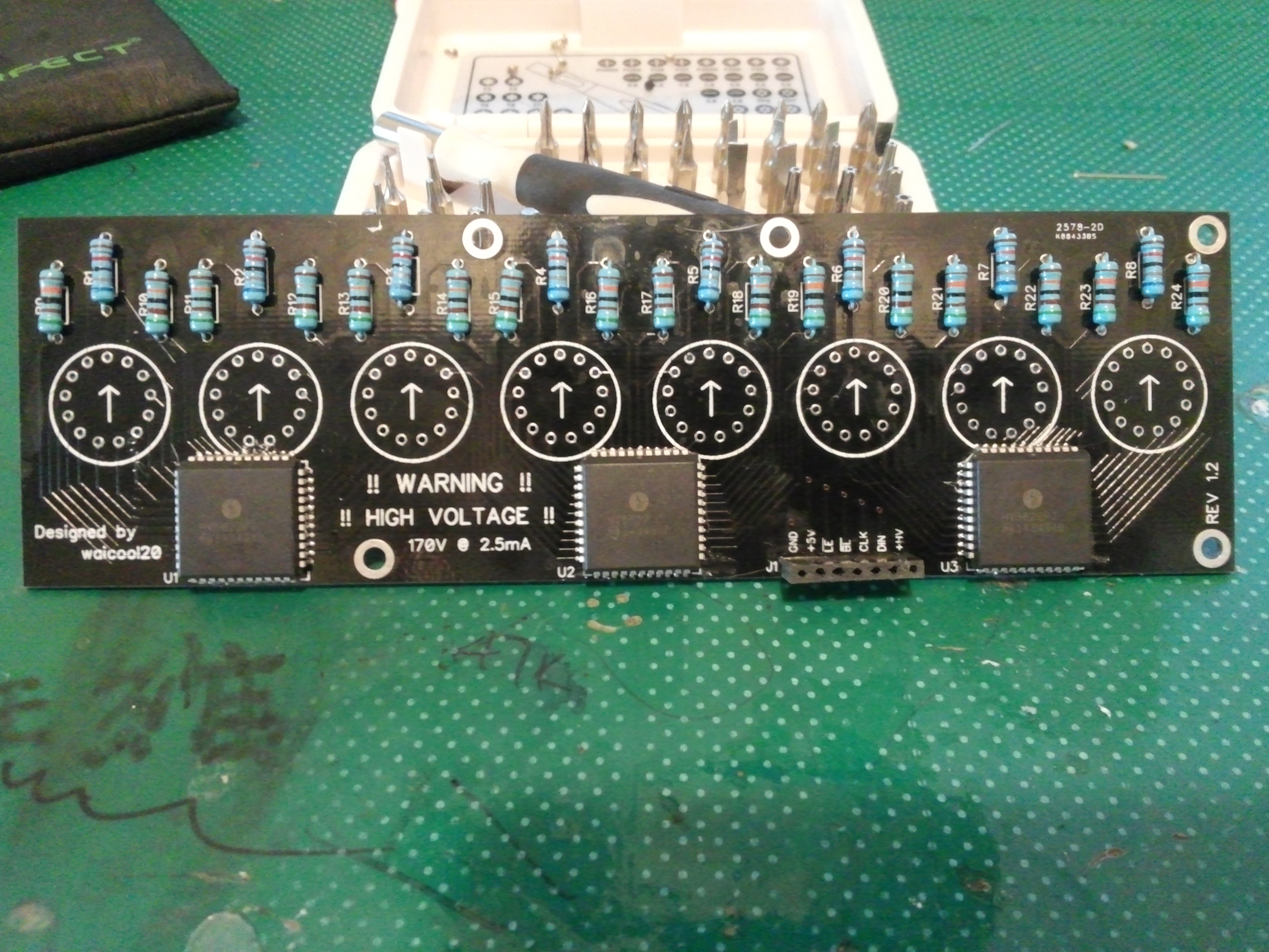
All the circuit boards are finally assembled!!! And I only can say THEY WORK!!! 😀 Though of course there are some parts of the design which make me think about my design skills :/ well pictures first!

So exams are done and hell that was crazy, 2 weeks of painful mind torture XD anyways today the Nixie Board of the Divergence Meter is finally assembled >.< !!!!!
Here are some pics 😀
Here we have the front view, nothing really special. Though the female pin headers had to be filed down a bit so that it would fit the height constraints and that’s why they look like that, but the electrical contact and tightness is still great. I didn’t really clean the board before taking a photo so uhh….deal with it :p

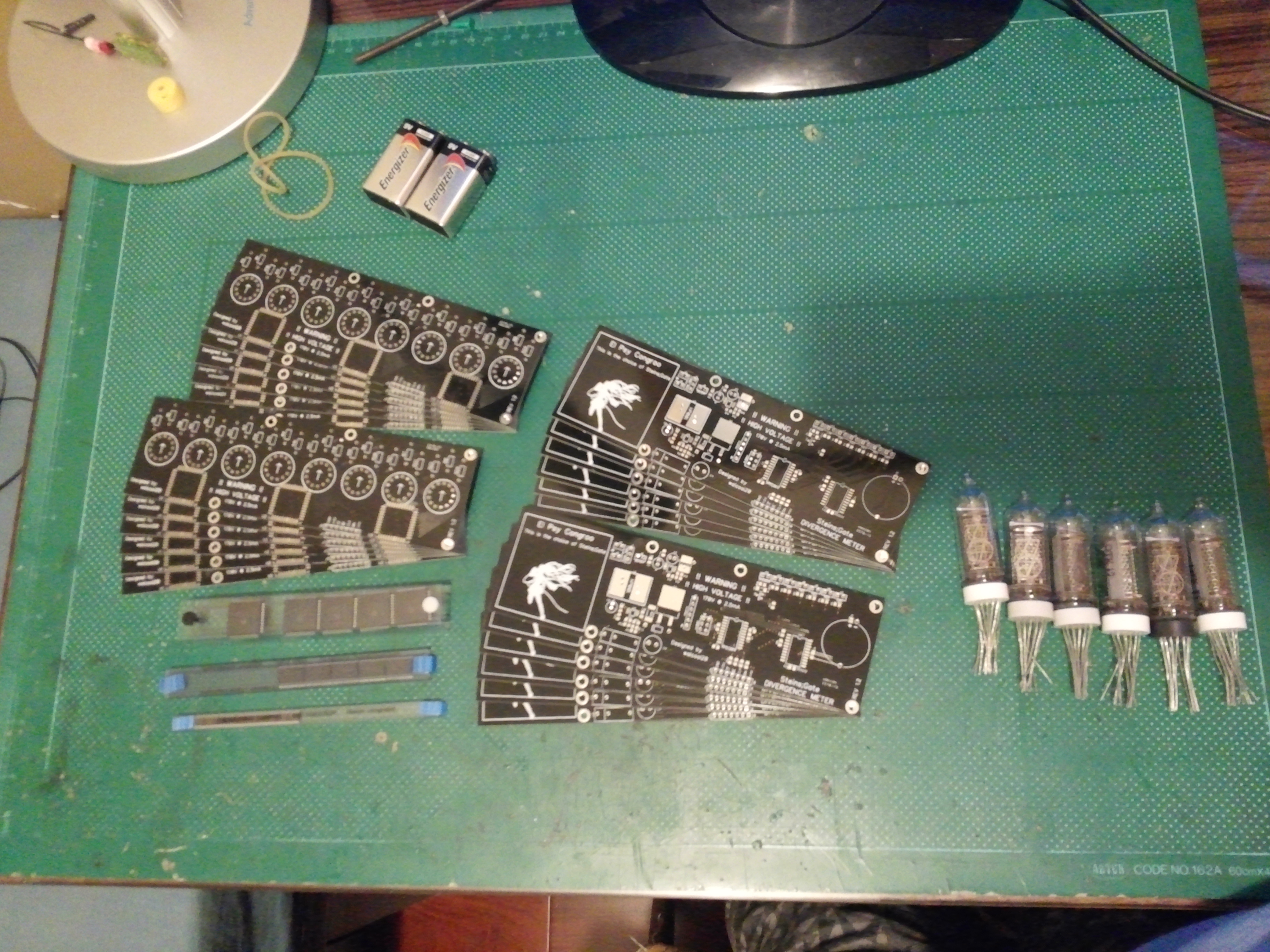
AND ITS HERE! The boards finally came from the fab and they surprisingly good for such a cheap price (~240HKD) They even sent an extra 2 for a total of 12 each 😀 )though the smaller print on the silkscreen is still missing that special touch but otherwise it looks really good.
Here’s a photo of the boards, some of the chips and the Nixie Tubes (only 6 T.T got to buy 2 more)

The left board is the Nixie Tube board where the HV5622 and the Nixies will sit and the right one is the Main board where the power supply and control circuitry go. The chips from top to bottom are HV5622, DS3232 and the MAX1771 (Not gonna use it in this design but it used to be on there!) I got those 3 chips for free as samples from Microchip and Maxim so big thanks to them! The tubes were from my sister so big thanks to her also!
Edit: It’s complete! Click here to go see it!
I’m currently making a divergence meter replica based on this guys design
Though of course I have added my own twist to it and have some added features.
The main differences are:
Other than that it should be largely the same 🙂
Here are some not so 3D 3D models :3
Main Board 3D Model:

(I didn’t know what to add in the battery area so i just stuck a Miku silhouette in there :3 )
Nixie Tube Board 3D Model:

Just to let you know I don’t even know if I can do this, so don’t get your hopes too high lol I just wanted to share this with you all~~~~~ I got most of the parts but I’m currently waiting for the PCBs to come from the fab so after that I’ll begin assembling it 😀 I hope in time for the summer anicon so that I can show it off :p oh and if you want you could give out some ideas that I can implement in software (not in hardware cuz thats already set in stone)
El Psy Congroo
waicool20
Want to continue? Go read Update 1!
NOTE: The divergence meter is a fictional device from the anime Steins;Gate, it’s used to calculate the Attractor Field of a universe/timeline so that they can be differentiated. For more information go to http://steins-gate.wikia.com/wiki/Divergence_Meter