User manual here written personally by me 😀
https://github.com/waicool20/Divergence-Meter-Project/blob/master/Users%20Manual.md
El Psy Congroo,
waicool20
User manual here written personally by me 😀
https://github.com/waicool20/Divergence-Meter-Project/blob/master/Users%20Manual.md
El Psy Congroo,
waicool20
*Drum Rolls* *Cheers* YES it’s finally complete :’) THE DIVERGENCE METER IS COMPLETE !!! It took me a long time, it took me a lot of effort, it also caused me a lot of headaches but hey its complete!!!! Really awesome indeed, though I still have to tweak it a bit in the software, somehow release 0.1.0a of the software uses up a whopping 6KB out of 8KB of program space, I really hope to optimize the code and make the world line rolling much more visually accurate, otherwise it’s really awesome to look at especially at night 😀 the way nixie tubes display numbers gives that really special retro feeling yet it gives a futuristic feeling at the same time.
Now for some power consumption reports, well so far I’ve only had the thing on batteries with the longest duration of 2 hours but according to my estimations, measurements and fooling around(writing it down makes it science ;D ), I’ve found that it should run for around 4 hours on the lowest brightness settings and 11 hours on the highest. One thing I did though design in an “adaptive brightness” feature into the thing. Basically it uses an LDR (Light Dependent Resistor) and the device measures the environments brightness, when it’s dark it turns the display darker to save power and when it’s bright it turns up the display to make it easier to see.
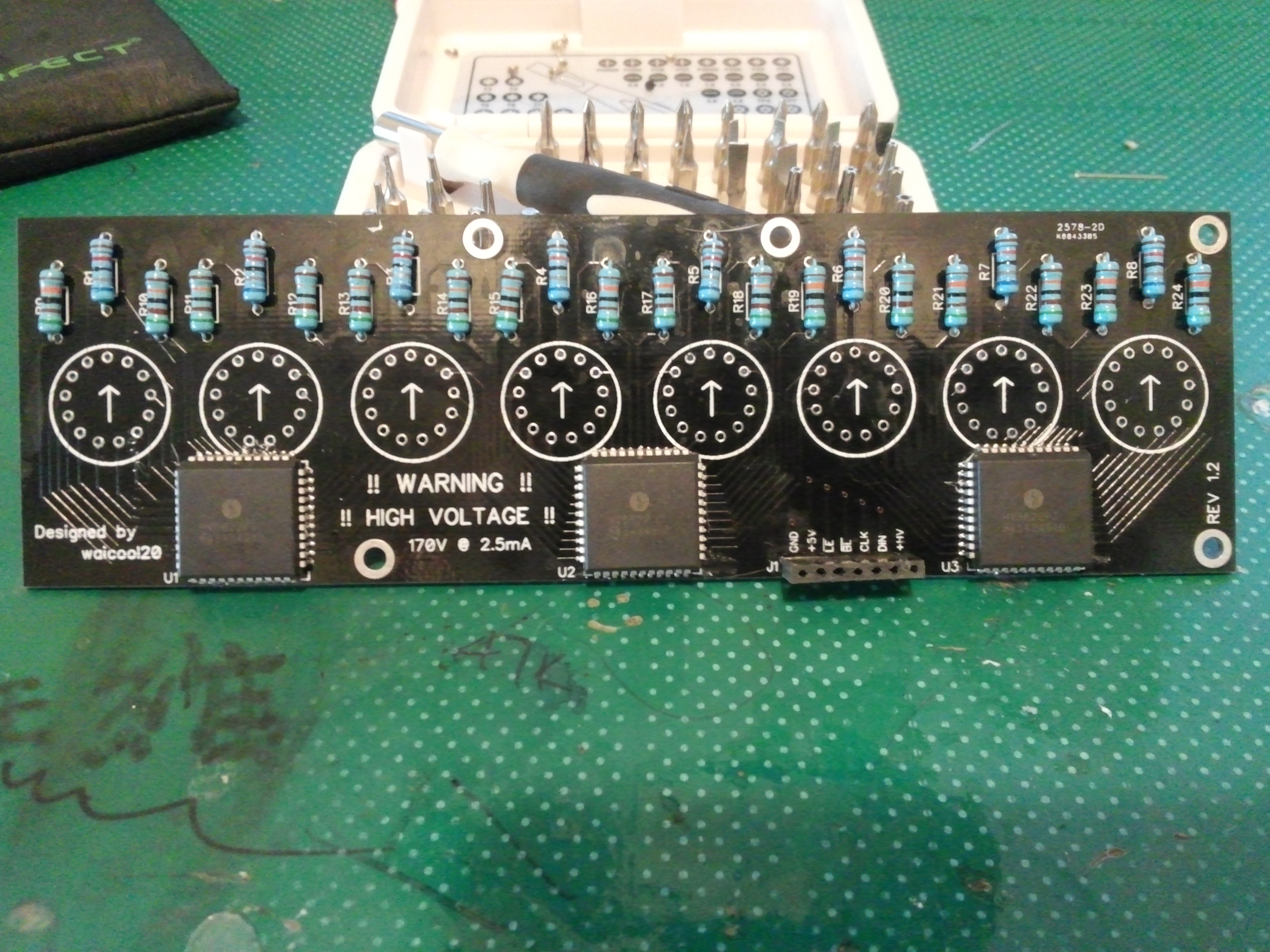
So exams are done and hell that was crazy, 2 weeks of painful mind torture XD anyways today the Nixie Board of the Divergence Meter is finally assembled >.< !!!!!
Here are some pics 😀
Here we have the front view, nothing really special. Though the female pin headers had to be filed down a bit so that it would fit the height constraints and that’s why they look like that, but the electrical contact and tightness is still great. I didn’t really clean the board before taking a photo so uhh….deal with it :p

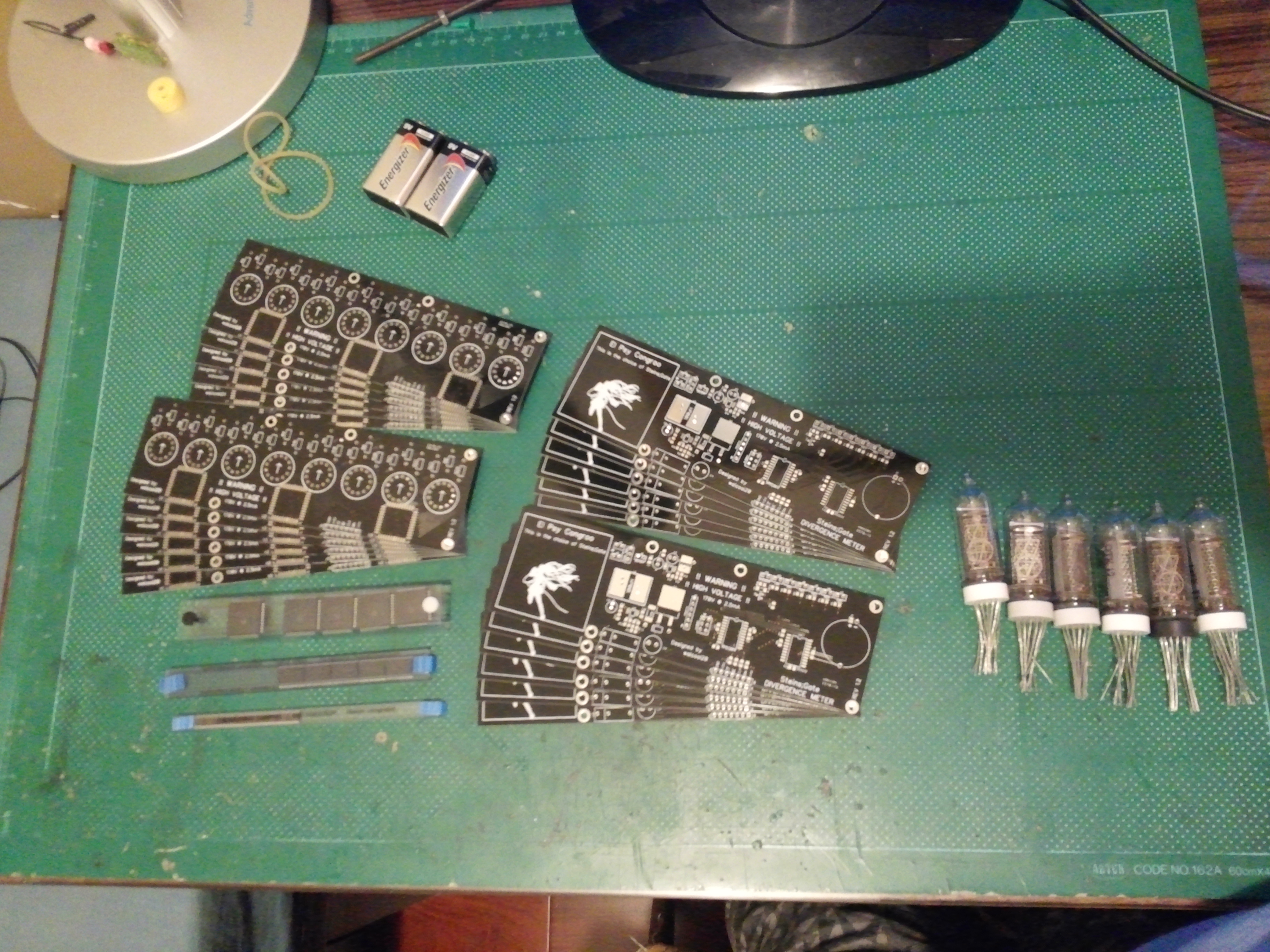
AND ITS HERE! The boards finally came from the fab and they surprisingly good for such a cheap price (~240HKD) They even sent an extra 2 for a total of 12 each 😀 )though the smaller print on the silkscreen is still missing that special touch but otherwise it looks really good.
Here’s a photo of the boards, some of the chips and the Nixie Tubes (only 6 T.T got to buy 2 more)

The left board is the Nixie Tube board where the HV5622 and the Nixies will sit and the right one is the Main board where the power supply and control circuitry go. The chips from top to bottom are HV5622, DS3232 and the MAX1771 (Not gonna use it in this design but it used to be on there!) I got those 3 chips for free as samples from Microchip and Maxim so big thanks to them! The tubes were from my sister so big thanks to her also!